Dual
Carburetor Synchronization
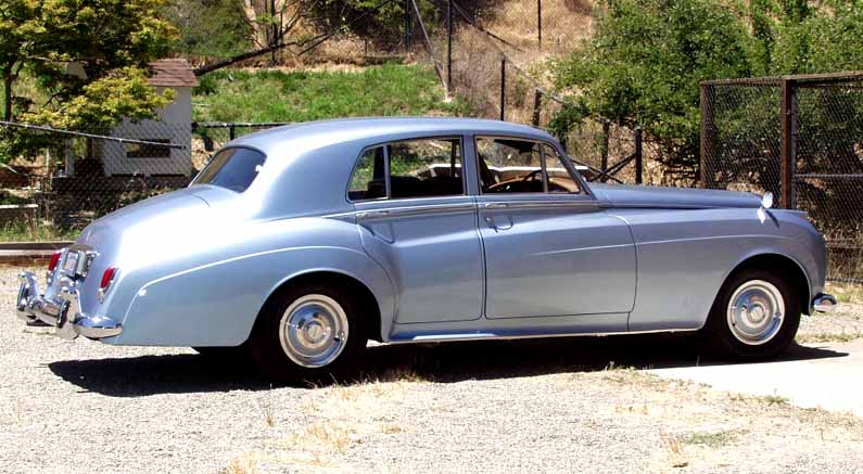
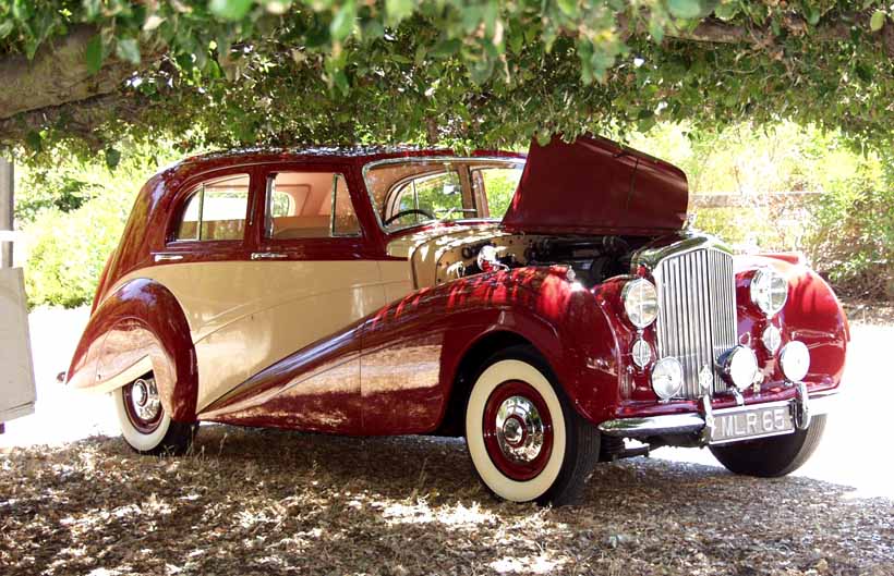
Rolls Royce Silver Cloud and Bentley S I
July 20, 2002 - Saratoga, CA (click for event Pix)
Jim Weager Presiding Technically
Hosts - Barbara & Austin Kilburn
click
on
the
title for PAGES:
TOOL
SUGGESTIONS…………………………………….…
2
A-
PRELIMINARY DISASSEMBLY………………………..
3
B-
CHECKING EQUAL
NEEDLE POSITION………….…
4
C-
THROTTLE PLATE
SYNCHRONIZATION…………….
5
D-
CARBURETOR SUCTION
CHAMBER ASSEMBLY…
6
E-
SETTING THROTTLE
LEVER CLEARANCE………...
7
F-
SYNCHRONIZATION OF
THE CARBURETORS……..
8
G-
IDLE SPEED
ADJUSTMENT……………………………
10
H-
MIXTURE ADJUSTMENT;
ROUGH…………………… 10
H-
MIXTURE ADJUSTMENT; FINE…………………………
11
I-
FINAL CHECK……………………………………………..11
J-
SETTING THE
FAST IDLE
CAM CLEARANCE……...11
K- FINAL ASSEMBLY……………………………………….. 12
THE STICKING PISTON…………………………………….. 12
Prior to attempting the
following procedure, it is assumed that the engine and the ignition system,
including the fuel pump, fuel filter and air filter are all in good working
order.
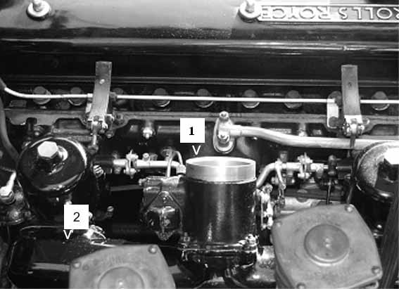
After the removal of the Air
Cleaner and Cold Air Runner, if you are absolutely certain that the needle
position is the same on both carburetors and positively sure that both throttle
plates are in synch with each other, you may begin at Step E- Setting Throttle
Lever Clearance.
Gasket (1) Choke Body to Cold Air Runner
Gaskets
(2) Cold Air Runner to Carburetor
Note: The use of the old gaskets is certainly
permissible. The key here is that
they are in good condition. Small
air leaks due to poor gaskets are not fatal because it represents an air leak
prior to the introduction of the fuel mixture.
A major cold air leak could create an audible hissing sound, weaken the
effect of the air cleaner, and most certainly implies maintenance practices
inconsistent with your PMC.
Note: The short length of
the tools, while not essential, will assist in the application of the tools in
tight places.
Screw Driver
7/16th inch box and open end wrench (suggest
4 inch length)
1/2 inch box and open end wrench (suggest 5 inch length)
13/16th inch box, open end or socket
9/32nd inch box and open end wrench (suggest 4 inch length)
Feeler Gauge (.0187 in.-.020 in. & .098 in.)
Steel Ruler, 6 in.
Putty Knife 1 inch or narrower
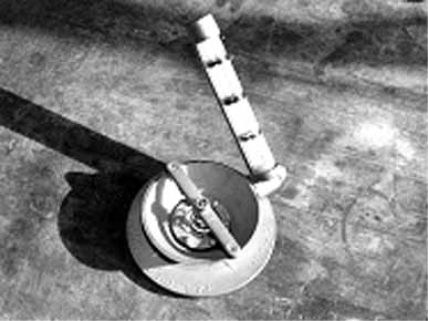
UNI-SYN
™ (flow gauge)*
Tachometer
Two (2) Strips of Typing Paper 1/4 in. x 6 in.
Fender Cover
Strong Box or Stool to stand on
*UNI-SYN
™ may be purchased from
Performance Products 1.800.423.3173. www.performanceproducts.com
$28.95
or
other performance or sports car supply source.
1.
Remove the air cleaner assembly from the Choke Body (Fig. A)
Caution:
Be careful in the following steps not to drop any nuts, lock washers or screws.
2. Remove the 4, 1/2 in. nuts and lock washers from the studs of the Cold Air
Runner
attached to the Carburetor Intake Throats.
3. Remove the 4, 7/16th in. nuts and lock washers from the studs of the Cold Air
Runner
attached to the Choke Body.
4. Remove the Cold Air Runner from the engine.
Note:
Be careful not to kink the vacuum tube or bend the linkage.
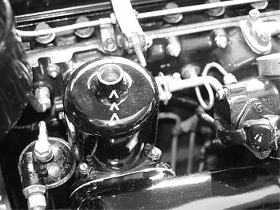
1. With a 13/16th in. wrench loosen and remove the Hydraulic Dampers from the
Piston Chambers. Be careful to note which damper belongs to which chamber. (Fig. B)
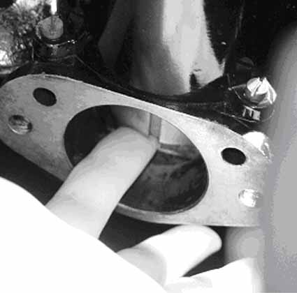
checking to see
that it moves freely and bottoms to the seat without binding. This will serve as a benchmark when performing step D-1.
(Fig. C)
If binding is present, go to THE STICKING PISTON found on the last page of this manual.
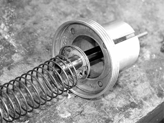
3. Remove the 4 screws which attach the Suction Chambers to the body of the Carburetor.
Be
careful when removing the chamber from the Carburetor Body.
There is a long spring inside the chamber at the end of which is a
perforated conical washer. (Fig. D)
Keep the correct chamber and spring/washer
with the correct damper and remember to which carburetor
body they belong.
4. Being careful not to apply side pressure, lift the Piston straight up out of the
Needle Jet. (Any side motion during this procedure could bend the Needle or damage the Needle Jet.)
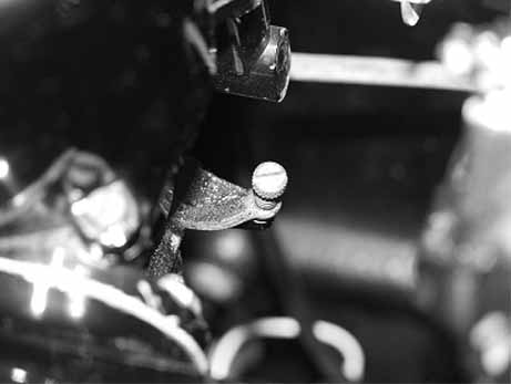
5. With the Steel Ruler, check to see that each needle extends the same distance
from the piston skirt. If not, adjust one of the needles to equal the other. This
can be achieved by loosening the set screw located on the side of the piston
skirt. Hint:
In most cases there is a ring groove cut into the shaft of the needle that acts
as a
visual assurance of proper positioning of the needle.
(Fig. E)
6. Check to be sure the Piston and the inner walls of the Suction Chamber are
free from heavy
carbon deposits. If cleaning
is in order, use carburetor cleaner or lacquer thinner and a soft rag. Under no circumstance
should you use steel wool or sandpaper on these surfaces. Proper tolerance
between piston and chamber is critical.
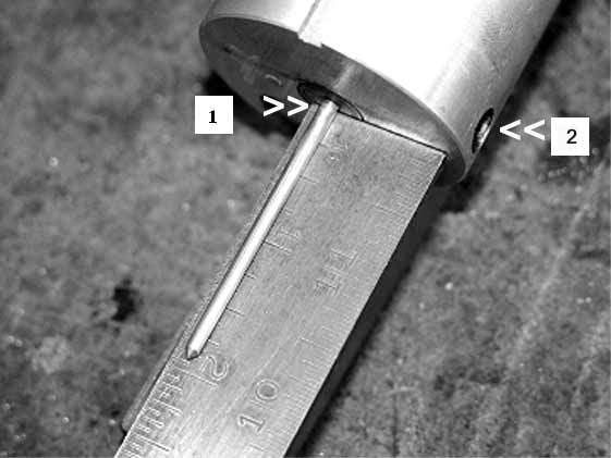
Fig.
E Confirming
length of needle extension
1. Ring Groove location 2. Needle Set Screw
C-
THROTTLE PLATE SYNCHRONIZATION
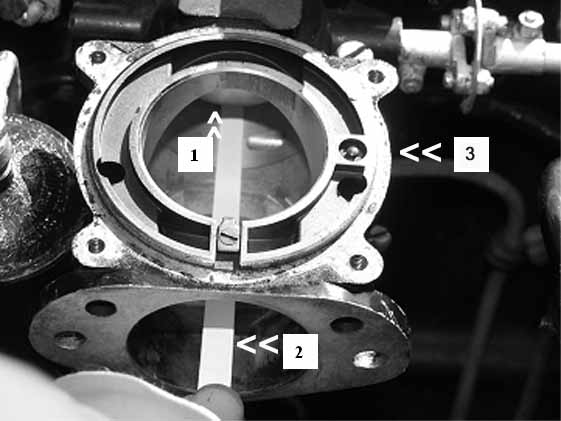
1.
Throttle Plate 2. Paper Strip
3. Lift Pin
Section D, Carburetor Suction Chamber Assembly.
3. Loosen the Pinch Bolts that are adjacent to the flexible couplings. Using your finger, gently push the throttle plate in each carburetor until it is closed. Retighten the Pinch Bolts. (Fig. G) Again try the test in Step 2.
four
screws which secure the Suction Chambers to the body of the Carburetor.
With the screws still loose, place a finger into the carburetor throat
and move the piston up and down (Fig. C),
checking to see that it moves freely and bottoms to the seat with out binding. While repeatedly moving the piston up and down, snug up one
screw and then the screw across from the first screw, continue the
tightening in a crisscross fashion until all are snug.
Check one more time for free piston movement.
Then repeat the same procedure on the second carburetor.
If binding occurs, wiggling the chambers around the axis of the mounting
screws, with the screws softly seated, should fix the problem. Note: If the pistons moved freely in step B-2, the lack of free movement
at this point is likely caused by play between the mounting screws and the
mounting holes in the flanges at the base of the Suction Chambers.
Should the wiggling of the Suction Chambers around the axis of the
mounting screws not solve the problem, you will have to check to see if you
might have accidentally bent the Needles in the handling process.
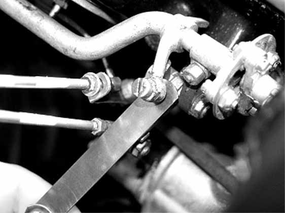
E- SETTING THROTTLE LEVER CLEARANCE
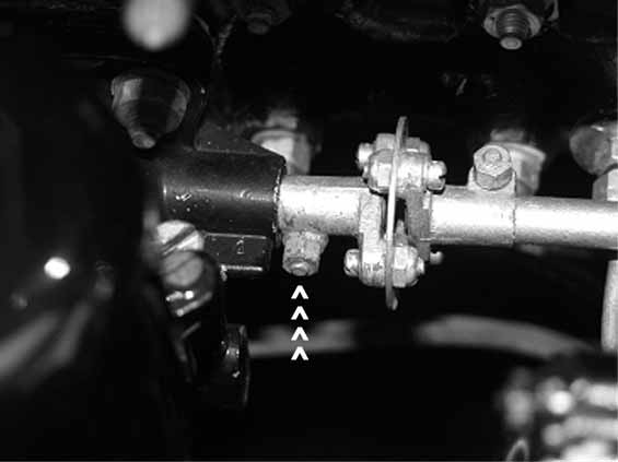
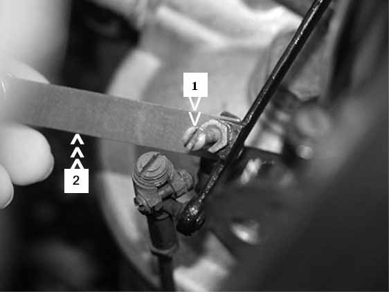
1. With the Throttle Stop Adjusting screw backed off from the Throttle Stop, place a
.0187 in.- .020 in. feeler gauge between the Throttle Stop and the tip of the
Throttle Stop
Adjusting Screw. Turn the Throttle
Stop Adjusting Screw in until it touches the feeler gauge.
(Fig. H)
The following procedures employ the use of the UNI-SYN ™ (flow gauge)
F-
SYNCHRONIZATION OF THE CARBURETORS
1.
Check to be certain that the Fast Idle Cam is disengaged from the Fast
Idle Set Screw. (Fig.
I)
2.
Turn in both of the Slow Running Adjusting Screws until they stop.
Now back the Slow Running Adjusting Screws out 2 turns. (Fig.
J)
3. Start the engine and hold the UNI-SYN ™ (flow gauge) against the intake bore of one carburetor. Note the position of the “pea” in the site glass of the flow gauge. Now place the flow gauge against the intake bore of the other carburetor and turn its Slow Running Screw in or out until the “pea” in the site glass is in the same position as on the previous carburetor. The carburetors are now synchronized. (Fig. K)
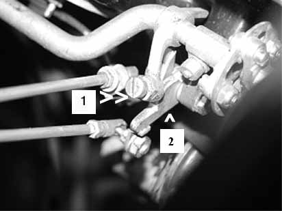
Fig. I
1.
Set Screw 2.
Fast Idle Cam
Fig.
J Slow
Running Adjustment 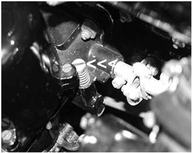
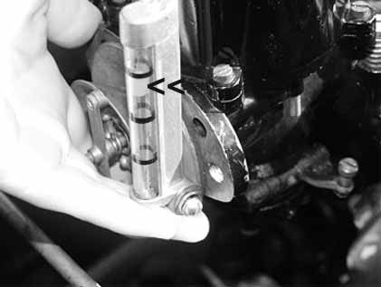
Fig.
K
Applying the UNI-SYN ™
The
Indicator Pea
Hint:
If the engine refuses to idle smoothly,
engage the Fast Idle Cam against the Set Screw one or two steps until the engine
is running smoothly. Let the engine continue to run until it has reached normal
operating temperature. Then once
again disengage the Fast Idle Cam from the Set Screw.
4. Attach the
Tachometer.
Screw
(to reduce idle speed), or turning out the Slow Running Adjustment Screw (to
increase the idle speed). Idle
Speed for Silver Cloud I and S 1 is 400 to 425 r.p.m. Remember, you are dealing
with two carburetors that both contribute to the idle speed on an individual
basis. When you turn one Slow
Running Screw in or out, you must turn the other Carburetor’s Slow Running
Screw the same amount. Make your
adjustments in small increments. (Fig. J)
Note: If you set the idle speed too high, by turning out the Slow Running Screws too far, the carburetors will whistle at speed.
1.
With the Fast Idle Cam still off the Set Screw (disengaged) and the
Tachometer still functioning, turn one of the Mixture Adjustment Screws out
until there is a change in the idle speed (it should drop in r.p.m.).
This is a lean mixture. (Fig. L)
2. Raise the engine speed for a few moments by lifting the Throttle Lever. This will
help to keep the spark plugs from fouling. This should be done periodically while
you
are executing the Mixture Adjustment.
3. Turn the Mixture Adjustment Screw in a half turn at a time until the engine is
running smoother.
4. Repeat the same process on the second carburetor.
Note: At this point the engine may be running nicely but the mixture must be tested to be sure it is correct for each carburetor.
5.
Lift the Mixture Adjusting Screw with your fingers about 1/16th
inch and hold
that position off the stop. If the mixture for that carburetor is correct, the
r.p.m. will increase slightly and then settle to the original speed.
If the r.p.m. drops and stays there the mixture is too lean.
If the r.p.m. increases and stays at that level, the mixture is too rich.
Alternate
Methode: Under each Suction Chamber is a Lift Pin. It is located on the right side of each carburetor. (Fig. F
No. 2) Push the Lift Pin up about
1/16th inch and hold as in Step 4.
The Lift Pin on the rear carburetor is easy to push with your finger. The
Lift Pin on the front carburetor is very difficult to push because of the Float
Bowl location. But it can be done.
Idle Speed for
Silver Cloud I and S I is 400 to
425 r.p.m.
For vehicles fitted with air conditioning, you may wish to increase
the idle speed to 550-600 r.p.m.
Note:
With the carburetors properly in synch, slow acceleration should yield smooth
response from the engine. No
shudder should be present.
J-
SETTING THE FAST IDLE CAM CLEARANCE
the Fast Idle Cam. Place a .098 in. feeler gauge between the Cam and the
Set
Screw. Turn the Set Screw in until
it touches the feeler gauge. (Fig.
M)
1.
Place a liberal coating of petroleum jelly or spray dry silicon on both
sides of the new gaskets. This will
allow disassembly at a later time with no damage to the gasket material.
2.
Replace the Cold Air Runner.
3.
Replace the Air Cleaner Assembly.
A sticking piston may be indicated by one or more of the following:
A. Stalling
B. Poor Slow Running
C. Lack of Power
D.
Abnormally High Fuel Consumption
A sticking piston, one which does not move
freely up and down, may be caused by one or more of the following maladies:
1. Carbon build up on the sides of the Piston Assembly
a. Remove the Suction Chamber as described in B- 3.
b. Follow the steps B- 4. and B- 6.
c.
If no carbon build is noted go to Step 2.
2. Fowled Needle
a. Lower the Jet by pulling up on the Mixture Lever which is attached to
the Mixture Adjusting Screw (Fig. L). If the binding goes away, the problem lies between the needle and the seat.
b. Centralize the Main Jet. The procedure is too involved to describe here. Refer to “Work Shop Manual for the Rolls-Royce Silver Cloud”, page K14, “Main Jet- to centralize”
3. Bent Needle
a. Loosen the Set Screw as described in B- 5.
b. Follow the steps as described in the “Note” in D- 1
 |
 |
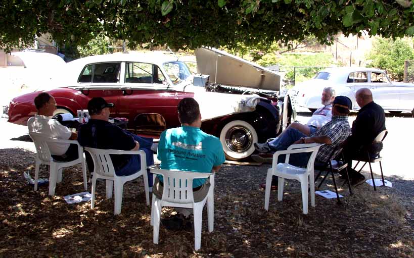 |
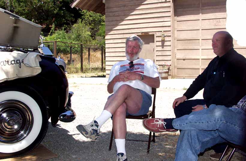
| (Jim) MAN! That's a good Question. | Austin....TRUST ME! (Jim) | Questions?...Naw-Swapping Lies |
 |
 |
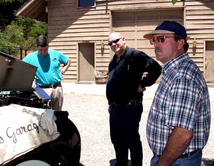 |
| (l to r) Rogers, Gallo, Murray | Well....back when I.... (Austin) | Can you imagine a garage AND a shade tree? Austin must have fallen into it! |
Other PMC Attending (click on any picture to enlarge it)
 |
 |
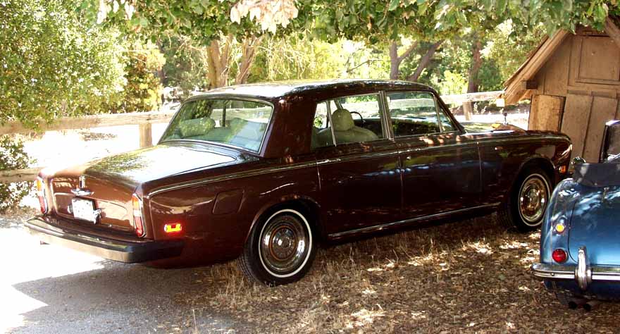 |
|
| Sally Marden's SI | Ivan Gallo's MK VI | Dave Roger's Shadow |