 |
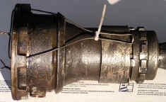
| The
"U" joint assembly |
| from
one end of the |
| drive
line before it was |
| cleaned. |
|
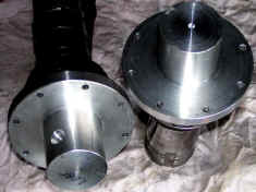 |
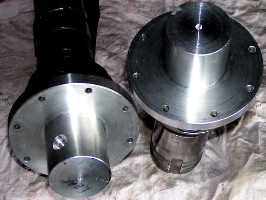
| Machined
adaptors to |
| fit
each end of the drive |
| line
to the balance |
| equipment
for spinning. |
|
 |
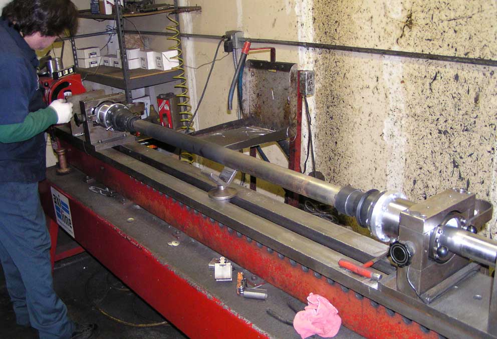
| This
is the equipment |
| used
to spin the drive |
| line
to determine |
| balance.
Here the |
| drive
line is mounted |
| and
in the process. |
|
 |
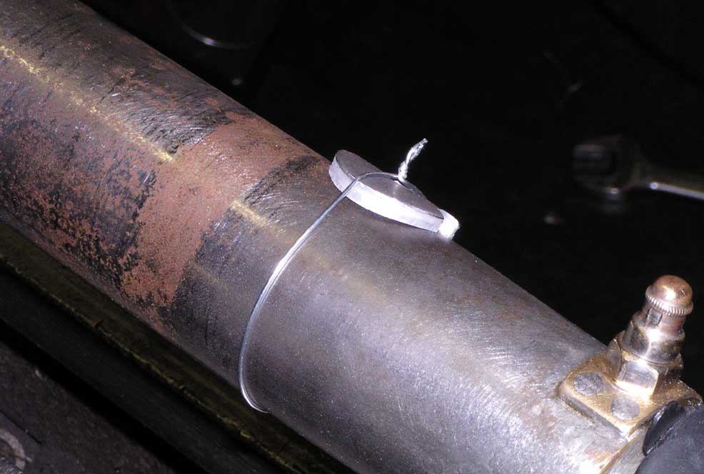
| A
balance weight fit |
| to
the drive line for |
| another
test spin. |
|
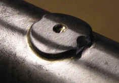 |
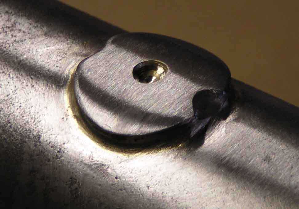
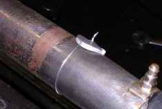
| A
balance weight that |
| I
brazed onto the drive |
| line
as indicated by the |
| spin
procedure. |
| Final
prep and finish |
| followed. |
|
 |
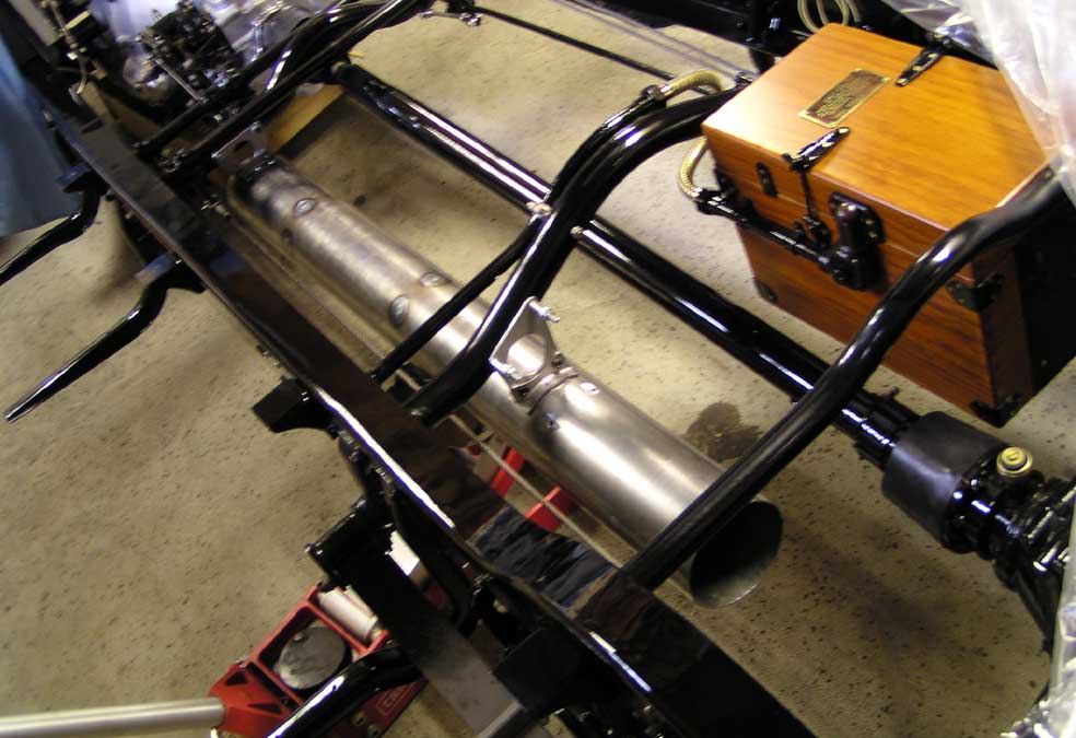
| The
drive line shown |
| installed
on the chassis. |
| You
can also see that |
| the
muffler is being |
| test
fit for hanger |
| adjustment. |
|
 Return
to Main Page
Return
to Main Page