ENGINE
Return to Main Page
Click on any Picture for Enlargement
The offside engine view
as of 1977
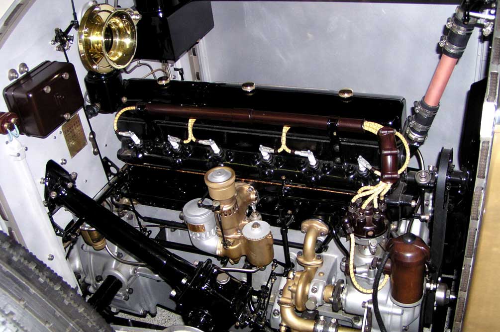
The offside view of the
completed engine bay.
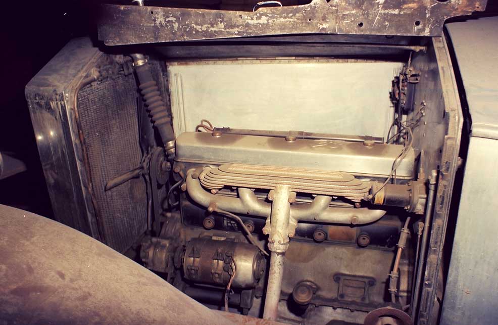
The nearside engine
view as of 1977.
The nearside view of the
nearly completed engine
bay.
The magneto and
exhaust pipe are not
in this view.
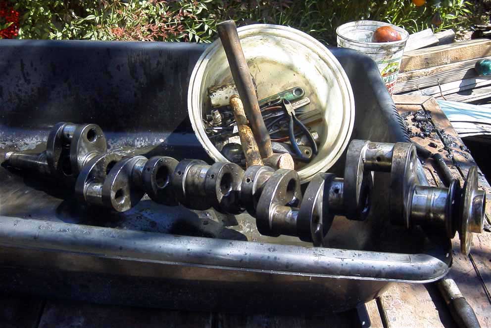
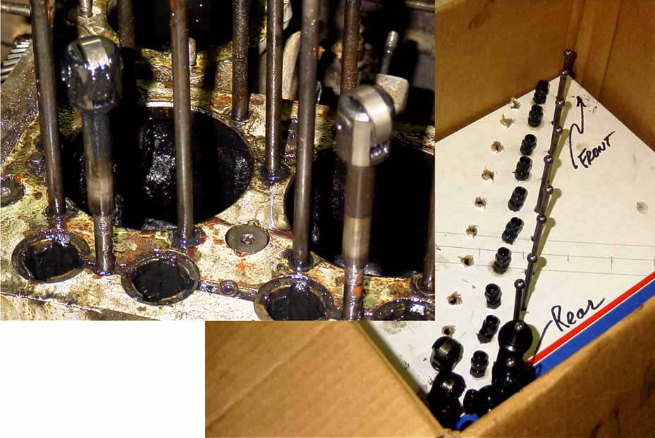
Note the crud found
in the crankshaft oil
passages.
Without
complete disassembly,
the oil would have been
unable to lubricate
main and rod bearings.
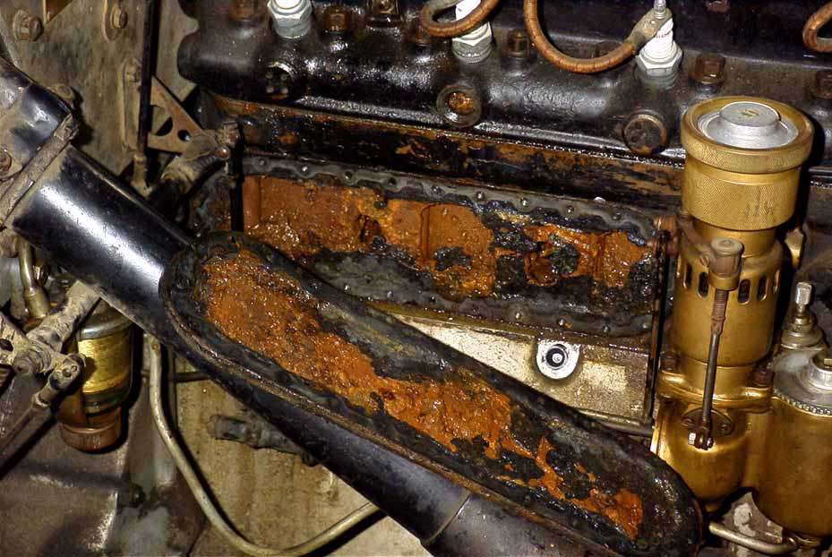
This shows the crud in
the coolant passages.
The engine ran well
but overheated.
The
complete rebuild
corrected many
problems that might not
have been found
otherwise.
The exhaust and intake
valve parts being
disassembled and
stored in proper order.
This includes the
pushrods, adjusters,
and roller lifters.
All
were found in good
condition once cleaned
except for the rollers
and pins.
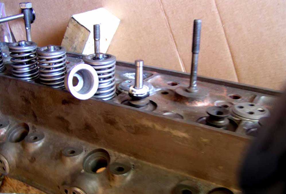
Assembly of the valves
and springs with Teflon
valve guides.
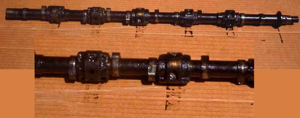
A close up and extended
view of the camshaft and
bearings.
These also
needed cleaning only .
Rollers had been gentle
on the cam surfaces.
Blocking the front six
coolant holes was a
1930 service bulletin
that was incorporated
for improved cooling.
Without this, coolant
returned up thru the
head and back to the
radiator without going
to the back of the engine.
With this and clean
passages, the car runs
nice and cool.
The cam roller pins
needed to be pressed
out of the followers.
Next, new rollers and
pins had to be pressed
back in.
The process required
a jig to prevent distorting
the followers. Careful
micrometer readings
before and after meant
a smooth assembly when
complete.
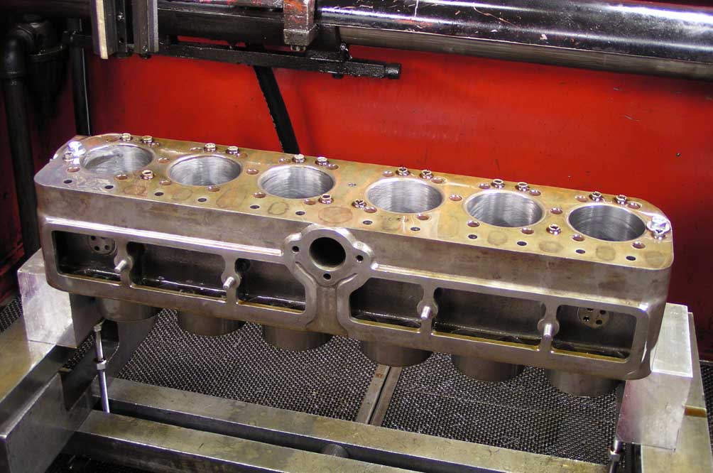
The block after the
cylinders had been thru
the power honing.\
process.
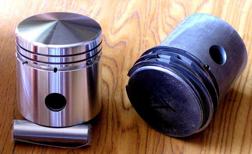
The new and old
pistons.
Note the old
pistons had 5 rings.
Modern pistons have 3
rings for less wear and
heat.
The new design
also has a slight dome
to increase compression.
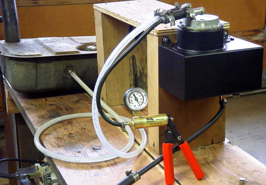
A vacuum tester used
to simulate engine
vacuum to check the
AutoVac.
Engine vacuumed pulls
petrol from the tank in
the rear and stores it
in the AutoVac for
gravity feed to the carb.
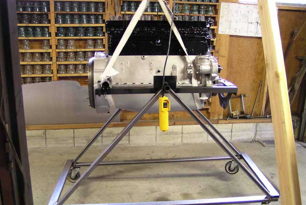
The engine being
assembled on a stand
that could rotate for
access to top or bottom
sides.
Here a strap is
being adjusted to lift
the engine back into
the chassis frame.
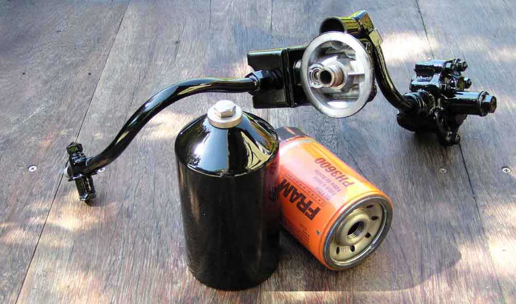
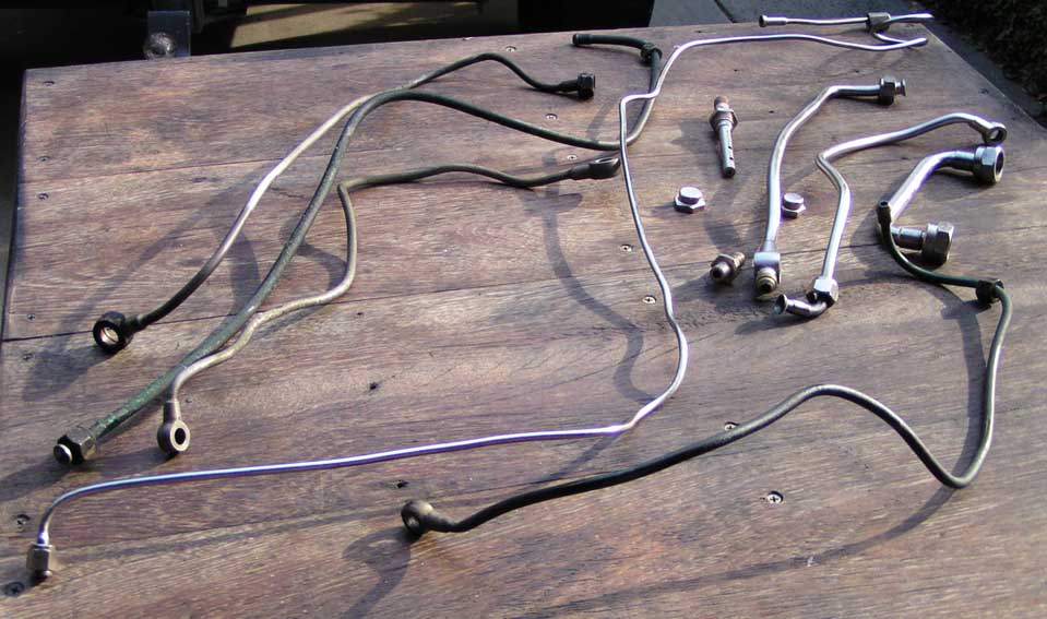
These are the lines and
fittings added to give the
engine it's first oil filter.
Note all parts are made
to look old and hide the
modern spin on filter.
Some of the many oil,
petrol, and vacuum
lines prior to cleaning.
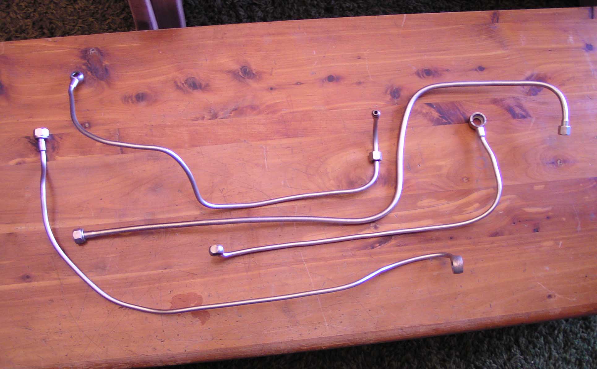
Various lines after
electroless nickel plating.
Return to Main Page
 Return
to Main Page
Return
to Main Page