A Vibration Damper Restoration
Return
to Main Page
![]() Click for Text of Removal Instructions
Click for Text of Removal Instructions
Click on any Picture for Enlargement
 |
Dynamo
Brake Drive
Removal (see text Button Above) |
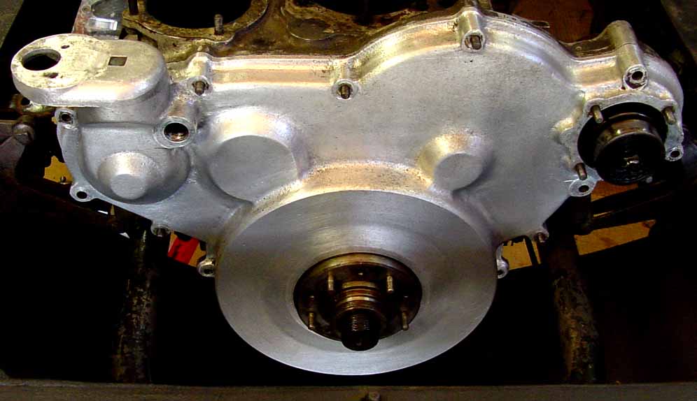 |
Timing Cover ready for Removal |
 |
Showing the Fan Pulley removed from the 5 bolts that also hold the starting dog nut locking plate | 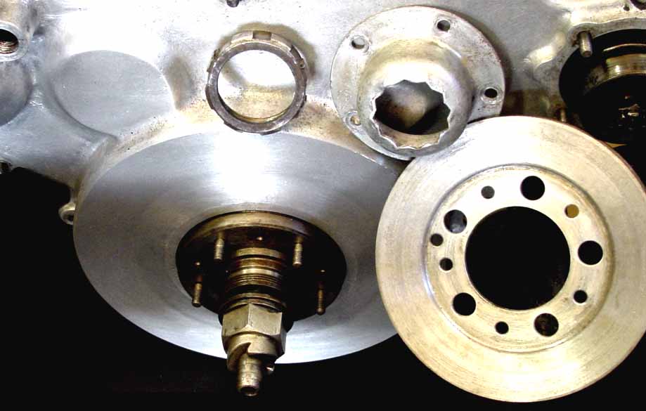 |
Showing the fan pulley, lock plate, and serrated nut (LH) removed |
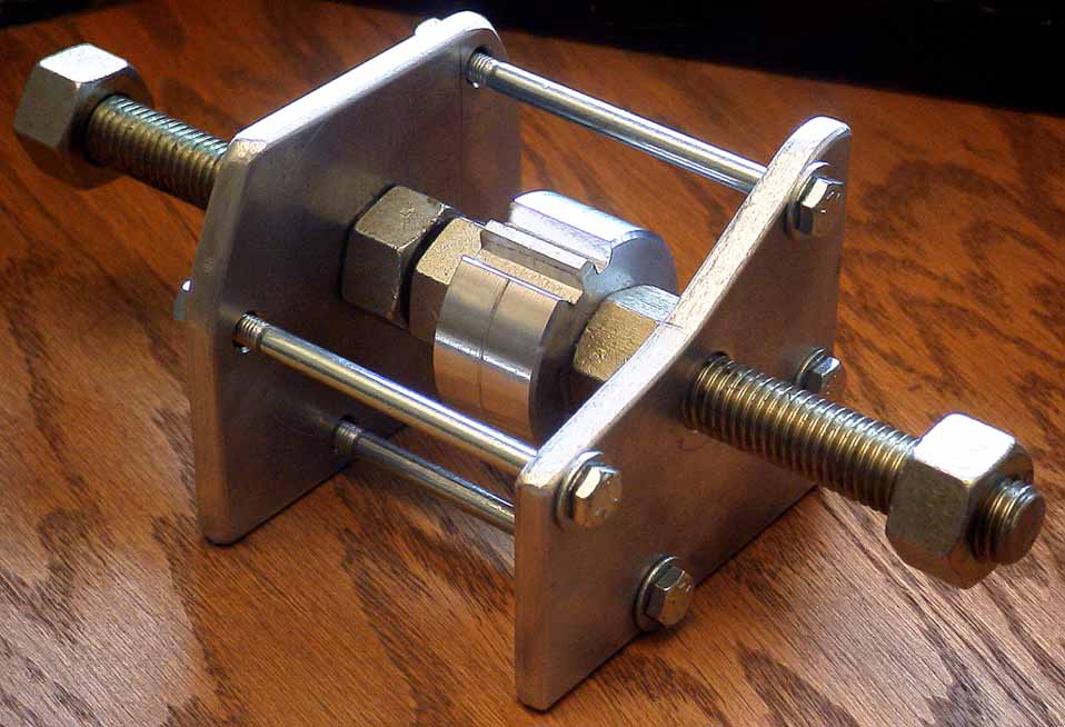 |
This tool is installed in place of the starter to lock the flywheel and crankcase from turning so the starting dog nut may be removed (RH) see also the tool section | 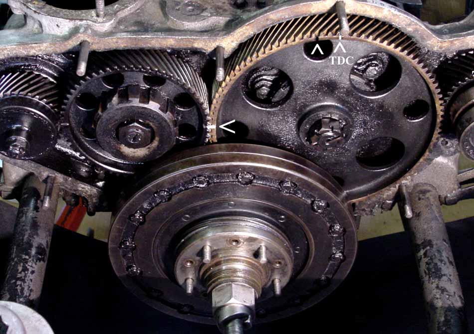 |
Showing the marks needed to get the cam timing correct upon re-assembly. It is easier to see what's happening with the starting dog nut removal with the cover off |
 |
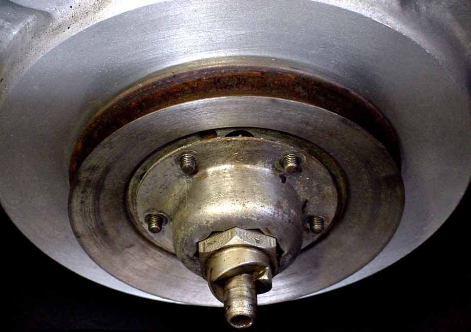
The nut is off and the tool installed (five nuts on the fan studs) ready for the removal of the actual damper by applying small and even torque on the outer 5 nuts one at a time. The force of the outer piece of the tool is exerted upon the end of the crankshaft while the tool studs pull the damper off the tapered shaft. Mine was on very tight and a loud report (rifle shot) sounded as it broke loose. One would think something broke, but examination showed about 1/8" gap leaving the tool to be removed before the removal of the damper by hand. Observe the rotation of the cam gear as the damper comes off. It is what has to be considered as the gears are reassembled. | 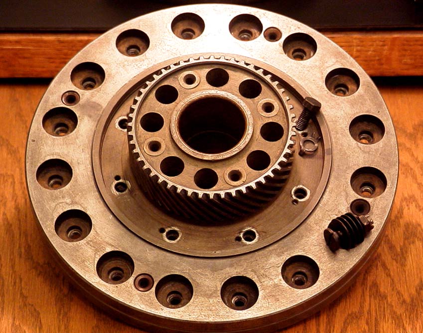 |
Damper off showing the gear that drives the cam. The outer ring of bolts (16) hold the two halves of the damper rings in place and are installed with springs to adjust the pressure on the friction material inside. These bolts go into threaded holes in the back half and also have lock nuts with cotter pins to hold the desired pressure for the life of the rebuild. |
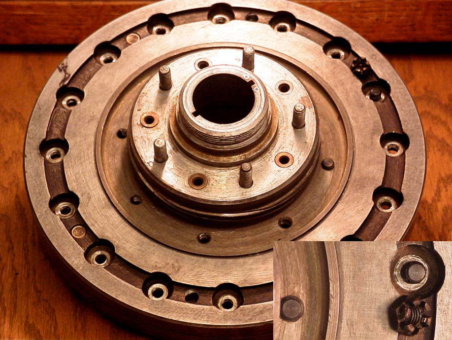 |
This shows the other side and detail of the inner and outer bolts. Remove the outer bolts from this side first, split the rings off, and then take the center apart | 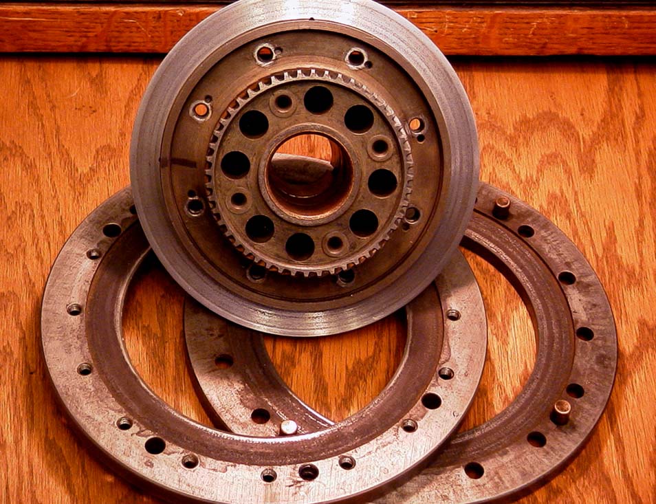 |
Showing the center and the rings apart. Here you will find worn or missing friction material around the inside of the outer rings |
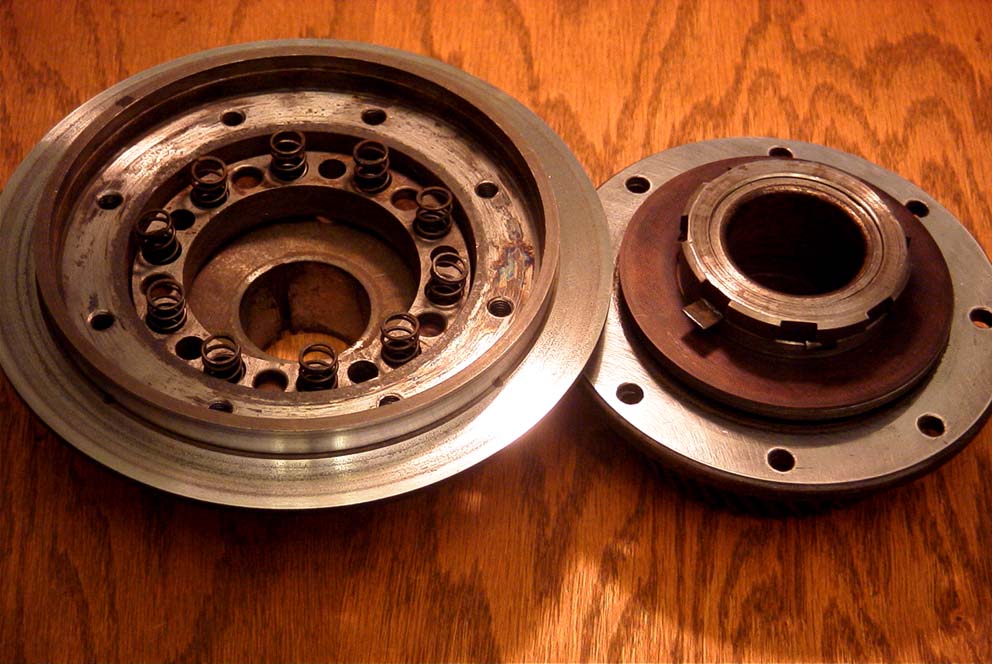 |
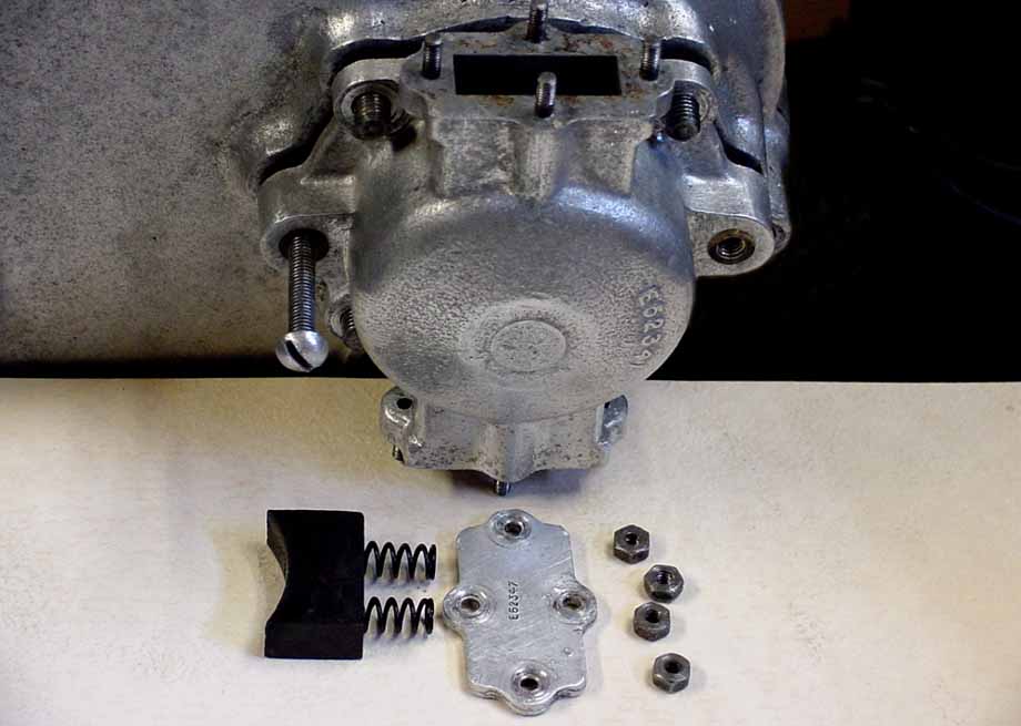
Showing the center assembly apart. Here you will find plenty of oily crud. The springs that apply pressure to the fiber center disks are shown. |  |
Shown is the center surface that mates with the outer rings after a dress up. Note the inside of the outer rings will require more than a fine paper dressing. One wants to get these smooth and true without removing too much material. |
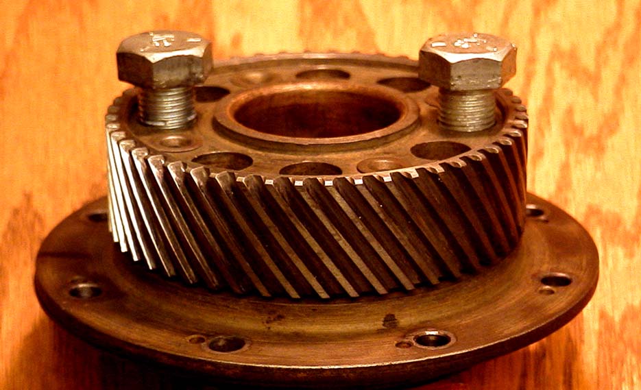 |
If you need to further disassemble the center assembly to replace or clean the fiber disks, check the tortional springs, or to clean everything, then you may want to fit snug bolts into the holes as shown. These can be firmly clamped into a vise without clamping the very obviously high tolerance surfaces. | 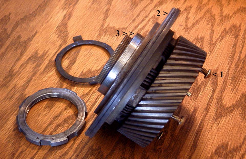 |
Keep in mind that when removing the serrated nut (RH), you will be twisting against the springs inside. I used an alloy bar as a drift to gently move the ring a little at a time after bending the locking tab out. The brass bolts (#1) shown on the right of this picture are inserted into four holes that go thru to the large ring (#2) to allow force on the smaller ring (#3) which is on a double keyed and tapered shaft. Be sure the brass bolts fit thru with little slop (I used #10 - 24's about 2" long) These will also clean the holes as they are gently hand guided thru. Brass rods of equal length may also be used. Just insert your choice and place the whole setup brass down on a hard level surface and tap the center shaft gently with a non marring mallet or block of wood until separation occurs. |