| Ever
wonder why the drive line on a (particularly early) RR/B does not show
the signs of balancing from the factory? I have not been able to
detect any on the late 1920's cars I have inspected. It could be:
1) They did a good job and built it in... no counter weights or drill holes needed 2) They didn't think it was important 3) They didn't know about such a procedure I doubt if the latter was the case. No matter, if the drive line components have been worked on, or there is some sign that anything was distorted, or you are in the process of a restoration, I was told to have it checked. Good Idea. Just not too simple to accomplish. To
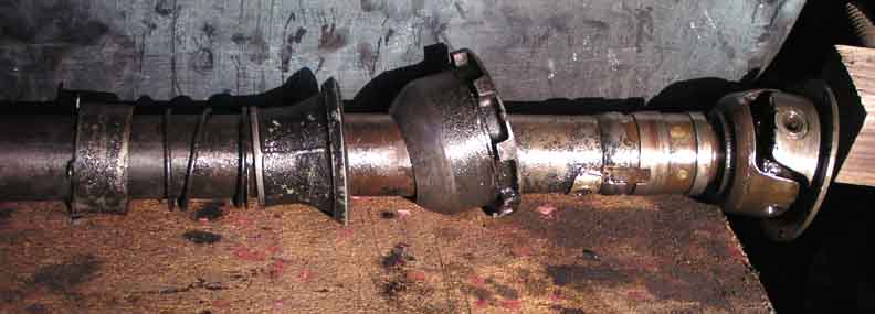
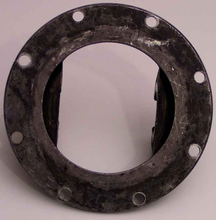
start, you have to disassemble and clean..... yuck! You then find out, drive line shops won't likely have an adaptor to put your drive line onto their balance jig which is basically a sophisticated and specialized lathe. I decided to machine adaptors to do that for my 1929 20HP (GEN 36). Following is the saga and results of that venture. First, I went to a local shop I know to be sympathetic to the automotive tinkerer. That is Drive Shaft Specialist, Steven Johnson. (see details below for the contact info). I showed him my drive line coupling.
He said "I can't do
that". I said "how about if I machine adaptors to your
equipment?" With a twinkle in his eye, he showed me what was
required. I mic'd the specs and went to the scrap metal seller
(Sim's Metal in San Jose) only to find that a lot of digging was
required to find the only 5 inch diameter aluminum round they had in the
whole yard. Then home to cut it in half (two hours) and put the
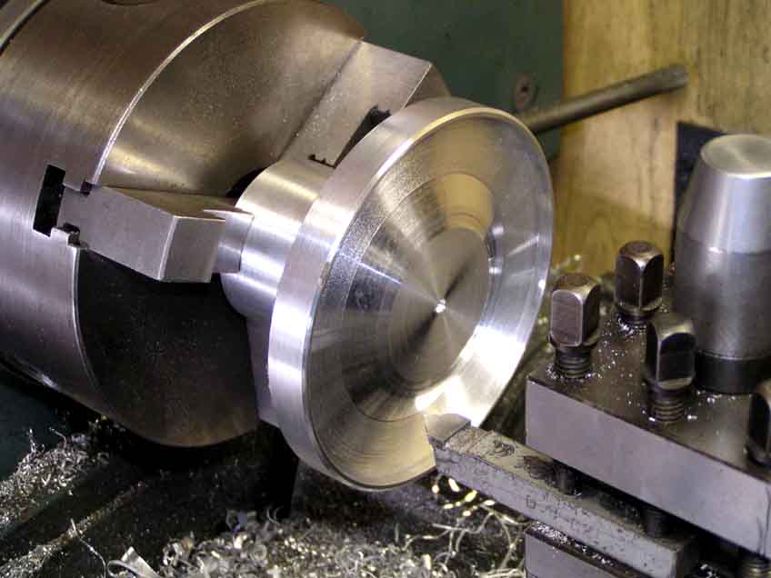
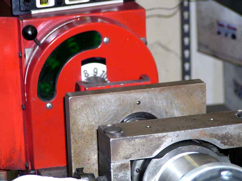
first half in the lathe to get started. This picture shows the start of the initial square up of the first end. About
four hours later, I had it roughed into the basic shape. Then it was time to let it cool to fine machine the final diameter of 2.250 inches onto the shaft to match his balance machine. Next, it turns around in the lathe to machine the interface to the drive line coupling.
Finally,
several hours later I have done two pieces and added the set screw holes
and the holes to bolt them to each end of the driveline. It
was now time to contact Steven and set up the time to
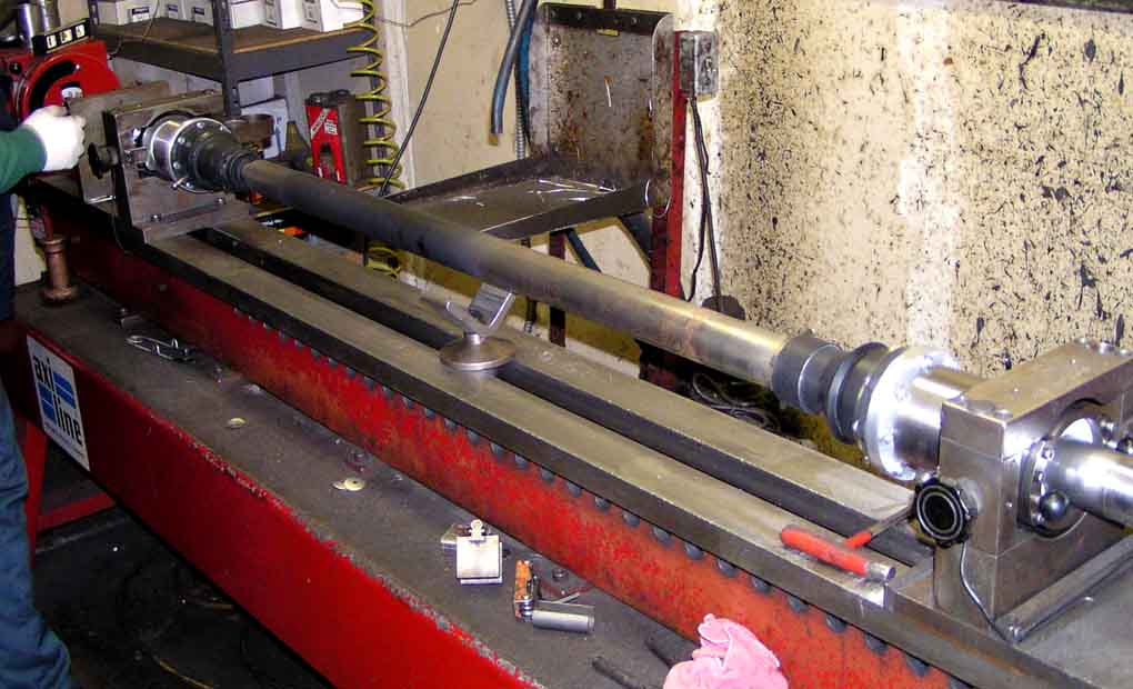
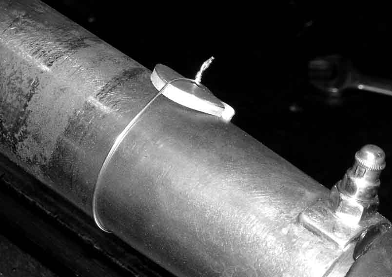
do the balancing act. He welcomed
me on a cold and wet morning and proceeded to get the driveline to the
balance machine. With a little fiddling, it was mounted and secured
for a "spin". Ok, so far so good, and Steve said it looked very straight. Alas, it was VERY out of balance! Several spins watching the strobe and RPM counters was required to get some weight on to start to true it.
|